Knowing the health of a system allows to guarante its efficiency and sustainability. The state observer is one of several techniques used by authors to estimate system state. This paper focuses on the problem of simultaneous states estimation of DC (Direct Current) and AC (Alternating Current) sides of a single-phase Photovoltaic (PV) grid-connected operating under the Sudanese-Sahelian climate of Cameroon. A generalized extended state observer (GESO) has been designed to simultaneously estimate the three states and the three disturbances of the system. A good estimation of the state and disturbances is achieved by the appropriate choice of the observer gain and the disturbance compensation gain resulting from the correct pole placement. The GESO robustness has been tested by varying the PV voltage and grid voltage. When there are no input fluctuations, the estimation errors of nominal states and disturbances converge to zero. The fluctuation in PV voltage resulting from partial shading has a significant impact on the boost converter current. The boost converter current varies proportionally with the drop in voltage due to partial shading from 55% to 59%. Under the grid voltage fluctuation, the boost converter current remains stable while the DC bus voltage and inverter current are significantly affected. The proposed GESO prove its robustness to perturbations from the PV array and grid side into the Single-Phase PV Grid-connected System. This paper contributes to the study of observers applied to the PV system and points the way to future work on diagnosing faults in PV systems operating in Cameroon's Sudanese-Sahelian climate.
| Published in | International Journal of Energy and Power Engineering (Volume 13, Issue 5) |
| DOI | 10.11648/j.ijepe.20241305.11 |
| Page(s) | 73-96 |
| Creative Commons |
This is an Open Access article, distributed under the terms of the Creative Commons Attribution 4.0 International License (http://creativecommons.org/licenses/by/4.0/), which permits unrestricted use, distribution and reproduction in any medium or format, provided the original work is properly cited. |
| Copyright |
Copyright © The Author(s), 2024. Published by Science Publishing Group |
Generalized Extended State Observer, Active Disturbance Rejection Control, PV Grid-Connected System, Sudanese-Sahelian Climate, Cameroon
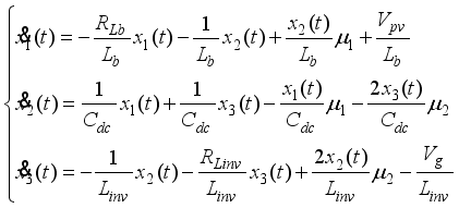
 (1)
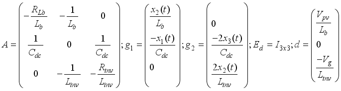
(1)  (2)
(2)  (3)
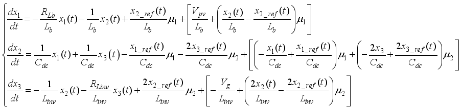
(3) 
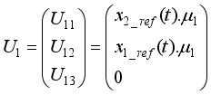
 (4)
(4)  (5)
(5)  (6)
(6)  ;
;  ; and matrices
  ;
;  ;
;  ;
; 
 (7)
(7)  , with
  ,
,  and
and  the state variable estimates of
  ,
,  and
and  , respectively. Matrix L
  (8)
(8)  (9)
(9)  (10)
(10)  (11)
(11)  (12)
(12) 
 (13)
(13)  (14)
(14) 
 (15)
(15)  and
and  as the system controls (boost converter and inverter controls respectively), and
  , a nonlinear function representing the nonlinearity of the system and the parts likely to be disturbed, the equation (15) becomes:
  (16)
(16)  (17)
(17) 
 ;
;  ;
;  ;
;  ;
; 
 ,
,  ,
,  ,
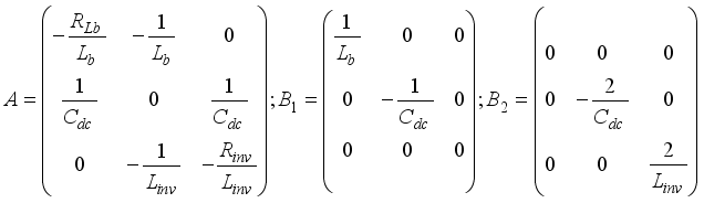
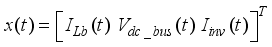
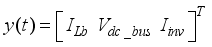
,  are the state vector, input, external disturbance, measurable outputs respectively. A is the state matrix of the nominal system with dimension
  ,
,  the control matrix of the nominal system with dimension
  , C the output matrix of the nominal system with dimension
  ,
,  and D, are
  dimension.
  be the order of the matrix A,
 (18)
(18)  (19)
(19)  ;
;  and
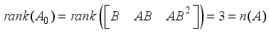
and  , the controllability matrix
  and the observability matrix
  are full rank. This means that the nominal system is controllable and observable, and therefore stable.
  to linearize the system (17), the extended state system is written as:
  (20)
(20)  ;
;  ;
; 
 ;
;  ;
;  ;
; 
 ;
; 
 be the order of the matrix
  ,
, 
 (21)
(21) 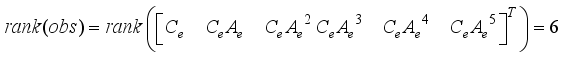 (22)
(22)  is the observability matrix rank and
  is the controllability matrix rank of the extended system. It’s verified that
 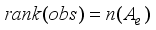 and
and 
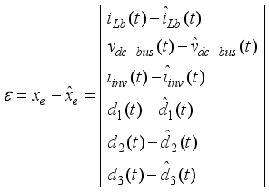
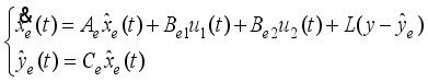 (23)
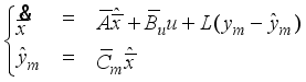
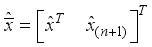
(23) 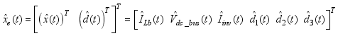 are the estimated state variables.
  is the extended state observer gain to be dimensioned.
  (24)
(24) 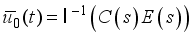 ,
,  is the internal model of reference input r(t),
  is the Laplace transform of tracking error e(t) = r(t) - y(t);
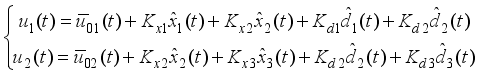
  the inverse Laplace transform; Kx is the state-feedback control gain; and Kd is the disturbance compensation gain.
  (25)
(25)  (26)
(26)  ;
;  ;
;  ;
;  ;
;  ;
;  ;
;  ;
; 
 (27)
(27)  et
et  ;
;  is a constant and
 (28)
(28)  (29)
(29)  is chosen so that
  is Hurwitz matrix, and then the observer error
  is bounded for any bounded disturbance
 and
and  are Hurwitz
  is possible noninvertible or even not a square matrix
  is invertible, then the disturbance compensation gain Kd takes the form:
  (30)
(30)  is Hurwitz;
  is Hurwitz;
  is invertible
  (31)
(31)  (32)
(32)  is Hurwitz.
  is Hurwitz.
  is inversible. If not, go to Step 2, and redesign Kx
 Parameter | Symbol | Value |
|---|---|---|
Photovoltaic generator voltage | Vpv | 120 V |
Boost converter inductance | Lb | 5 mH |
Internal resistance of converter | RLb | 1 Ω |
Boost converter current | ILb | 12 A |
DC bus capacitance | Cdc | 2.85 mF |
DC bus voltage | Vdc_bus | 240 V |
Inverter inductance | Linv | 5.16 mH |
Internal resistance of inverter | Rinv | 1 Ω |
Inverter current | Iinv | 6 A |
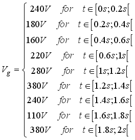
Grid voltage | Vg | 220 V |
Switching frequency | fc | 20 kHz |
Sample time | t | 10-5 S |
 (33)
(33)  are the eigenvalues of matrix
  .
.  and
and  are Hurwitz, the poles of both the closed-loop system and the ESO can be placed arbitrarily
 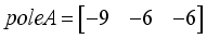 , the feedback control gain matrix is
 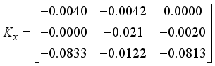 (34)
(34)  are:
are: 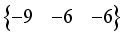
 is Hurwitz. The nominal system is therefore stable. The disturbance compensation gain Kd is obtained as follows:
 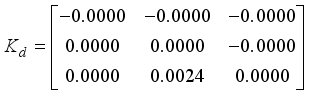 (35)
(35)  ; observer gain matrix L is obtained as:
 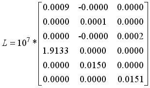 (36)
(36)  are:
are:  .
.  is Hurwitz ensuring the stability of GESO.
 Nominal Vpv Voltage: 120 V | ||
|---|---|---|
Shading | Voltage drop | Operating voltage |
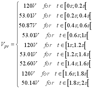
60 % | 55.78 % (66.93 V) | 53.01 V |
65 % | 56.17 % (67.40 V) | 52.60 V |
70 % | 56.39 % (67.66 V) | 52.34 V |
80 % | 57.61 % (69.13 V) | 50.87 V |
85 % | 57.83 % (69.39 V) | 50.61 V |
90 % | 57.72 % (69.26 V) | 50.74 V |
95 % | 58.22 % (69.86 V) | 50.14 V |
 (37)
(37)  (38)
(38)  are Hurwitz matrices.
 Vpv | Photovoltaic Generator Voltage |
Lb | Boost Converter Inductance |
RLb | Internal Resistance of Converter |
ILb | Boost Converter Current |
Cdc | DC Bus Capacitance |
Vdc_bus | DC Bus Voltage |
Linv | Inverter Inductance |
Rinv | Internal Resistance of Inverter |
Iinv | Inverter Current |
Vg | Grid Voltage |
d1, d2, d3 | Disturbances |
Kd | Compensation Gain |
L | Observer Gain |
Kx | State Feedback Control Gain |
A | State Matrix of the Nominal System |
Bi | Control Matrix of the Nominal System |
C | Output Matrix of the Nominal System |
Ae | State Matrix of the Extended System |
Bei | Control Matrix of the Extended System |
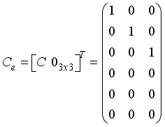
Ce | Output Matrix of the Extended System |
A0 | Controllability Matrix of the Nominal System |
C0 | Observability Matrix of the Nominal System |
GESO | Generalized Extended State Observer |
ADRC | Active Disturbance Rejection Control |
PV | Photovoltaic |
GADRC | Generalized Active Disturbance Rejection Control |
UV | Ultraviolet |
IR | Infrared |
PL | Photoluminescence |
EL | Electroluminescence |
SMO | Sliding Mode Observer |
UIO | Unknown Input Observer |
LO | Learning Observers |
EID | Equivalent Input Disturbance |
ESO | Extended State Observer |
LDUE | Linear Disturbance and Uncertainty Estimation |
NDUE | Nonlinear Disturbance and Uncertainty Estimation |
PID | Proportional-Integral-Derivative |
LCL | Inductor (L) - Capacitor (C) - Inductor (L) |
AD | Active Damping |
PWM | Pulse Width Modulation |
MOSFET | Metal-Oxide-Semiconductor Field-Effect Transistor |
IGBT | Insulated-Gate Bipolar Transistor |
| [1] | T. Kousksou, P. Bruel, A. Jamil, T. El Rha, and Y. Zeraouli, “Solar Energy Materials & Solar Cells Energy storage : Applications and challenges,” Sol. energy Mater. Sol. cells, vol. 120, pp. 59–80, 2014, |
| [2] | M. P. Clark et al., “Characterizing Uncertainty of the Hydrologic Impacts of Climate Change,” Curr. Clim. Chang. Reports, vol. 2, no. 2, pp. 55–64, 2016, |
| [3] | A. D. Dhass, N. Beemkumar, S. Harikrishnan, and H. M. Ali, “A Review on Factors Influencing the Mismatch Losses in Solar Photovoltaic System,” Int. J. Photoenergy, vol. 2022, 2022, |
| [4] | T. F. Wu, C. H. Chang, L. C. Lin, and C. L. Kuo, “Power loss comparison of single- and two-stage grid-connected photovoltaic systems,” IEEE Trans. Energy Convers., vol. 26, no. 2, pp. 707–715, 2011, |
| [5] | S. Daliento et al., “Monitoring, diagnosis, and power forecasting for photovoltaic fields: A review,” Int. J. Photoenergy, vol. 2017, 2017, |
| [6] | A. Livera, M. Theristis, G. Makrides, and G. E. Georghiou, “Recent advances in failure diagnosis techniques based on performance data analysis for grid-connected photovoltaic systems,” Renew. Energy, vol. 133, pp. 126–143, 2019, |
| [7] | H. Kazemi and A. Yazdizadeh, “Optimal state estimation and fault diagnosis for a class of nonlinear systems,” IEEE/CAA J. Autom. Sin., vol. 7, no. 2, pp. 517–526, 2020, |
| [8] | J. Han, “From PID to active disturbance rejection control,” IEEE Trans. Ind. Electron., vol. 56, no. 3, pp. 900–906, 2009, |
| [9] | D. Kharrat, H. Gassara, A. El Hajjaji, and M. Chaabane, “Adaptive Observer and Fault Tolerant Control for Takagi-Sugeno Descriptor Nonlinear Systems with Sensor and Actuator Faults,” Int. J. Control. Autom. Syst., vol. 16, no. 3, pp. 972–982, 2018, |
| [10] | X. J. Li, J. J. Yan, and G. H. Yang, “Adaptive Fault Estimation for T-S Fuzzy Interconnected Systems Based on Persistent Excitation Condition via Reference Signals,” IEEE Trans. Cybern., vol. 49, no. 8, pp. 2822–2834, 2019, |
| [11] | Z. Gao, X. Shi, and S. X. Ding, “Fuzzy state/disturbance observer design for T-S fuzzy systems with application to sensor fault estimation,” IEEE Trans. Syst. Man, Cybern. Part B Cybern., vol. 38, no. 3, pp. 875–880, 2008, |
| [12] | X. Liu, Z. Gao, and M. Z. Q. Chen, “Takagi-Sugeno Fuzzy Model Based Fault Estimation and Signal Compensation with Application to Wind Turbines,” IEEE Trans. Ind. Electron., vol. 64, no. 7, pp. 5678–5689, 2017, |
| [13] | F. Benyamina, A. Benrabah, F. Khoucha, M. F. Zia, Y. Achour, and M. Benbouzid, “An augmented state observer-based sensorless control of grid-connected inverters under grid faults,” Int. J. Electr. Power Energy Syst., vol. 133, no. December 2020, p. 107222, 2021, |
| [14] | M. Liu, X. Cao, and P. Shi, “Fuzzy-model-based fault-tolerant design for nonlinear stochastic systems against simultaneous sensor and actuator faults,” IEEE Trans. Fuzzy Syst., vol. 21, no. 5, pp. 789–799, 2013, |
| [15] | M. Li, M. Liu, Y. Zhang, and Y. Geng, “Fault tolerant sliding mode control for T-S fuzzy stochastic time-delay system via a novel sliding mode observer approach,” Int. J. Syst. Sci., vol. 49, no. 7, pp. 1353–1367, 2018, |
| [16] | H. Zhang, J. Han, Y. Wang, and X. Liu, “Sensor Fault Estimation of Switched Fuzzy Systems With Unknown Input,” IEEE Trans. Fuzzy Syst., vol. 26, no. 3, pp. 1114–1124, 2018, |
| [17] | J. Lan and R. J. Patton, “Integrated Design of Fault-Tolerant Control for Nonlinear Systems Based on Fault Estimation and T-S Fuzzy Modeling,” IEEE Trans. Fuzzy Syst., vol. 25, no. 5, pp. 1141–1154, 2017, |
| [18] | Q. Jia, W. Chen, Y. Zhang, and H. Li, “Fault reconstruction and fault-tolerant control via learning observers in Takagi-Sugeno fuzzy descriptor systems with time delays,” IEEE Trans. Ind. Electron., vol. 62, no. 6, pp. 3885–3895, 2015, |
| [19] | Q. Jia, W. Chen, Y. Zhang, and H. Li, “Fault reconstruction for Takagi-Sugeno fuzzy systems via learning observers,” Int. J. Control, vol. 89, no. 3, pp. 564–578, 2016, |
| [20] | W. H. Chen, D. J. Ballance, P. J. Gawthrop, and J. O’Reilly, “A nonlinear disturbance observer for robotic manipulators,” IEEE Trans. Ind. Electron., vol. 47, no. 4, pp. 932–938, 2000, |
| [21] | S. J. Kwon and W. K. Chung, “A discrete-time design and analysis of perturbation observer for motion control applications,” IEEE Trans. Control Syst. Technol., vol. 11, no. 3, pp. 399–407, 2003, |
| [22] | J. H. She, M. Fang, Y. Ohyama, H. Hashimoto, and M. Wu, “Improving disturbance-rejection performance based on an equivalent-input-disturbance approach,” IEEE Trans. Ind. Electron., vol. 55, no. 1, pp. 380–389, 2008, |
| [23] | Z. Gao, Y. Huang, and J. Han, “An alternative paradigm for control system design,” Proc. IEEE Conf. Decis. Control, vol. 5, pp. 4578–4585, 2001, |
| [24] | W. H. Chen, J. Yang, L. Guo, and S. Li, “Disturbance-Observer-Based Control and Related Methods - An Overview,” IEEE Trans. Ind. Electron., vol. 63, no. 2, pp. 1083–1095, 2016, |
| [25] | S. Li, J. Yang, W. H. Chen, and X. Chen, “Generalized extended state observer based control for systems with mismatched uncertainties,” IEEE Trans. Ind. Electron., vol. 59, no. 12, pp. 4792–4802, 2012, |
| [26] | P. Shah and B. Singh, “Adaptive Observer Based Control for Roof-Top Solar PV System,” IEEE Trans. Power Electron., vol. 35, no. 9, pp. 9402–9417, 2020, |
| [27] | M. Alshiekh, A. Marouf, and M. Kubeitari, “Current Control and Active Damping for Single Phase LCL-Filtered Grid Connected Inverter,” J. Control Sci. Eng., vol. 2020, 2020, |
| [28] | M. Mokhlis, M. Ferfra, and R. El Idrissi, “High gain observer-based control for grid-connected pv system under partial shading effect,” Int. J. Intell. Eng. Syst., vol. 13, no. 2, pp. 161–181, 2020, |
| [29] | J. Wang, S. Li, J. Yang, B. Wu, and Q. Li, “Extended state observer-based sliding mode control for PWM-based DC-DC buck power converter systems with mismatched disturbances,” IET Control Theory Appl., vol. 9, no. 4, pp. 579–586, 2015, |
| [30] | B. Wang, Z. Shen, H. Liu, and J. Hu, “Linear ADRC direct current control of gridconnected inverter with LCL filter for both active damping and grid voltage induced current distortion suppression,” IET Power Electron., vol. 11, no. 11, pp. 1748–1755, 2018, |
| [31] | Y. Zhu and J. Fei, “Disturbance Observer Based Fuzzy Sliding Mode Control of PV Grid Connected Inverter,” IEEE Access, vol. 6, pp. 21202–21211, 2018, |
| [32] | B. Guo, S. Bacha, M. Alamir, A. Hably, and C. Boudinet, “Generalized Integrator-Extended State Observer with Applications to Grid-Connected Converters in the Presence of Disturbances,” IEEE Trans. Control Syst. Technol., vol. 29, no. 2, pp. 744–755, 2021, |
| [33] | P. Jain et al., “A luenberger observer-based fault detection and identification scheme for photovoltaic DC-DC converters,” Proc. IECON 2017 - 43rd Annu. Conf. IEEE Ind. Electron. Soc., vol. 2017-Janua, pp. 5015–5020, 2017, |
| [34] | L. Qin, “Control of Single Phase LCL Photovoltaic Grid-Gonnected Inverter Based on State Observer,” Proc. 2020 IEEE Int. Conf. Power, Intell. Comput. Syst. ICPICS 2020, pp. 762–765, 2020, |
| [35] |
A. Ayang, “Diagnostic d’un système photovoltaïque à stockage par estimation paramétrique et commandes ADRC, intégré à une centrale autonome de cogénération d’énergie,” 2020. [Online]. Available:
https://constellation.uqac.ca/6499/1/Ayang_uqac_0862D_10767.pdf |
| [36] | L. Zhou, L. Cheng, C. Pan, and Z. Jiang, “Generalized Extended State Observer Based Speed Control for DC Motor Servo System,” Chinese Control Conf. CCC, vol. 2018-July, pp. 221–226, 2018, |
| [37] | M. A. Khan, S. Member, A. Haque, S. Member, and V. S. Bharath, “Dynamic Voltage Support for Low Voltage Ride Through Operation in Single-Phase Grid-Connected Photovoltaic Systems,” IEEE Trans. Power Electron., vol. 8993, no. c, 2021, |
| [38] | S. Sarikh, M. Raoufi, A. Bennouna, and B. Ikken, “Characteristic curve diagnosis based on fuzzy classification for a reliable photovoltaic fault monitoring,” Sustain. Energy Technol. Assessments, vol. 43, no. December 2020, p. 100958, 2021, |
| [39] | H. Renaudineau, J. Martin, S. Member, and S. Pierfederici, “DC-DC Converters Dynamic Modeling with State Observer-Based Parameter Estimation,” EEE Trans. POWER Electron., vol. 8993, no. c, pp. 1–9, 2014, |
| [40] | R. Errouissi and A. Al-durra, “Extended high-gain observer-based DC-link voltage regulation in dual-stage grid-tied PV system under balanced and unbalanced voltages,” IET Renew. Power Gener., vol. 14, no. 12, pp. 2037–2046, 2020, |
| [41] | L. Xu, R. Ma, S. Zhuo, R. Xie, X. Wang, and Y. Huangfu, “Observer Based Switch Open-Circuit Diagnosis for Interleaved Boost Converter,” IECON Proc. (Industrial Electron. Conf., vol. 2020-Octob, pp. 5012–5017, 2020, |
| [42] | B. Wang, Y. Xu, Z. Shen, J. Zou, C. Li, and H. Liu, “Current Control of Grid-Connected Inverter with LCL Filter Based on Extended-State Observer Estimations Using Single Sensor and Achieving Improved Robust Observation Dynamics,” IEEE Trans. Ind. Electron., vol. 64, no. 7, pp. 5428–5439, 2017, |
| [43] | W. Xue, W. Bai, S. Yang, and K. Song, “ADRC With Adaptive Extended State Observer and its Application to Air – Fuel Ratio Control in Gasoline Engines,” IEEE Trans. Ind. Electron., vol. 62, no. August, pp. 5847–5857, 2015, |
| [44] | Yaouba et al., “An Experimental and Case Study on the Evaluation of the Partial Shading Impact on PV Module Performance Operating Under the Sudano-Sahelian Climate of Cameroon,” Front. Energy Res., vol. 10, no. August, pp. 1–13, 2022, |
| [45] | L. Zhou, L. Cheng, J. She, and Z. Zhang, “Generalized extended state observer–based repetitive control for systems with mismatched disturbances,” Int. J. Robust Nonlinear Control, vol. 29, no. 11, pp. 3777–3792, 2019, |
| [46] | R. Madoński and P. Herman, “Survey on methods of increasing the efficiency of extended state disturbance observers,” ISA Trans., vol. 56, pp. 18–27, 2015, |
| [47] | M. A. Mahmud, H. R. Pota, M. J. Hossain, and S. Member, “Nonlinear Current Control Scheme for a Single-Phase Grid-Connected Photovoltaic System,” IEEE Trans. Sustain. ENERGY, vol. 5, no. 1, pp. 218–227, 2014, |
APA Style
Yaouba, Ayang, A., Tom, A., Djongyang, N. (2024). Adaptive Generalized Extended State Observer for a Single Phase PV Grid-connected System Operating Under the Sudanese-Sahelian Climate of Cameroon. International Journal of Energy and Power Engineering, 13(5), 73-96. https://doi.org/10.11648/j.ijepe.20241305.11
ACS Style
Yaouba; Ayang, A.; Tom, A.; Djongyang, N. Adaptive Generalized Extended State Observer for a Single Phase PV Grid-connected System Operating Under the Sudanese-Sahelian Climate of Cameroon. Int. J. Energy Power Eng. 2024, 13(5), 73-96. doi: 10.11648/j.ijepe.20241305.11
@article{10.11648/j.ijepe.20241305.11,
  author = {Yaouba and Albert Ayang and Ahmat Tom and Noël Djongyang},
  title = {Adaptive Generalized Extended State Observer for a Single Phase PV Grid-connected System Operating Under the Sudanese-Sahelian Climate of Cameroon
},
  journal = {International Journal of Energy and Power Engineering},
  volume = {13},
  number = {5},
  pages = {73-96},
  doi = {10.11648/j.ijepe.20241305.11},
  url = {https://doi.org/10.11648/j.ijepe.20241305.11},
  eprint = {https://article.sciencepublishinggroup.com/pdf/10.11648.j.ijepe.20241305.11},
  abstract = {Knowing the health of a system allows to guarante its efficiency and sustainability. The state observer is one of several techniques used by authors to estimate system state. This paper focuses on the problem of simultaneous states estimation of DC (Direct Current) and AC (Alternating Current) sides of a single-phase Photovoltaic (PV) grid-connected operating under the Sudanese-Sahelian climate of Cameroon. A generalized extended state observer (GESO) has been designed to simultaneously estimate the three states and the three disturbances of the system. A good estimation of the state and disturbances is achieved by the appropriate choice of the observer gain and the disturbance compensation gain resulting from the correct pole placement. The GESO robustness has been tested by varying the PV voltage and grid voltage. When there are no input fluctuations, the estimation errors of nominal states and disturbances converge to zero. The fluctuation in PV voltage resulting from partial shading has a significant impact on the boost converter current. The boost converter current varies proportionally with the drop in voltage due to partial shading from 55% to 59%. Under the grid voltage fluctuation, the boost converter current remains stable while the DC bus voltage and inverter current are significantly affected. The proposed GESO prove its robustness to perturbations from the PV array and grid side into the Single-Phase PV Grid-connected System. This paper contributes to the study of observers applied to the PV system and points the way to future work on diagnosing faults in PV systems operating in Cameroon's Sudanese-Sahelian climate.
},
 year = {2024}
}
TY  - JOUR
T1  - Adaptive Generalized Extended State Observer for a Single Phase PV Grid-connected System Operating Under the Sudanese-Sahelian Climate of Cameroon

AU  - Yaouba
AU  - Albert Ayang
AU  - Ahmat Tom
AU  - Noël Djongyang
Y1  - 2024/11/11
PY  - 2024
N1  - https://doi.org/10.11648/j.ijepe.20241305.11
DO  - 10.11648/j.ijepe.20241305.11
T2  - International Journal of Energy and Power Engineering
JF  - International Journal of Energy and Power Engineering
JO  - International Journal of Energy and Power Engineering
SP  - 73
EP  - 96
PB  - Science Publishing Group
SN  - 2326-960X
UR  - https://doi.org/10.11648/j.ijepe.20241305.11
AB  - Knowing the health of a system allows to guarante its efficiency and sustainability. The state observer is one of several techniques used by authors to estimate system state. This paper focuses on the problem of simultaneous states estimation of DC (Direct Current) and AC (Alternating Current) sides of a single-phase Photovoltaic (PV) grid-connected operating under the Sudanese-Sahelian climate of Cameroon. A generalized extended state observer (GESO) has been designed to simultaneously estimate the three states and the three disturbances of the system. A good estimation of the state and disturbances is achieved by the appropriate choice of the observer gain and the disturbance compensation gain resulting from the correct pole placement. The GESO robustness has been tested by varying the PV voltage and grid voltage. When there are no input fluctuations, the estimation errors of nominal states and disturbances converge to zero. The fluctuation in PV voltage resulting from partial shading has a significant impact on the boost converter current. The boost converter current varies proportionally with the drop in voltage due to partial shading from 55% to 59%. Under the grid voltage fluctuation, the boost converter current remains stable while the DC bus voltage and inverter current are significantly affected. The proposed GESO prove its robustness to perturbations from the PV array and grid side into the Single-Phase PV Grid-connected System. This paper contributes to the study of observers applied to the PV system and points the way to future work on diagnosing faults in PV systems operating in Cameroon's Sudanese-Sahelian climate.

VL  - 13
IS  - 5
ER  -
Department of Renewable Energy, National Advance School of Engineering of Maroua, University of Maroua, Maroua, Cameroon; Research Centre for Renewable Energy, Institute of Geological and Mining Research, Yaoundé, Cameroon
Department of Renewable Energy, National Advance School of Engineering of Maroua, University of Maroua, Maroua, Cameroon
Department of Energy Engineering, University Institute of Technology, University of Ngaoundéré, Ngaoundéré, Cameroon
Department of Renewable Energy, National Advance School of Engineering of Maroua, University of Maroua, Maroua, Cameroon
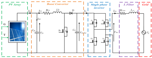
Figure 1. System equivalent circuit.
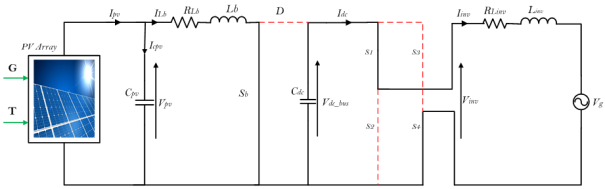
Figure 2. Energy accumulation phase 1.
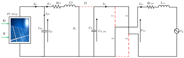
Figure 3. Energy accumulation phase 2.
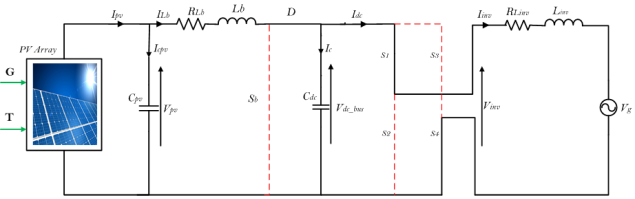
Figure 4. Energy transfer phase 1.
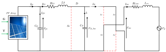
Figure 5. Energy transfer phase 2.
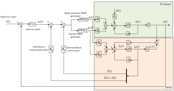
Figure 6. Configuration of the proposed GESO-based control system.
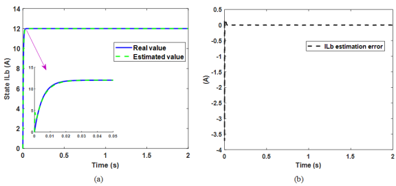
Figure 7. Response curves of the real and estimated boost converter inductance current ILb (a) and estimation error (b).
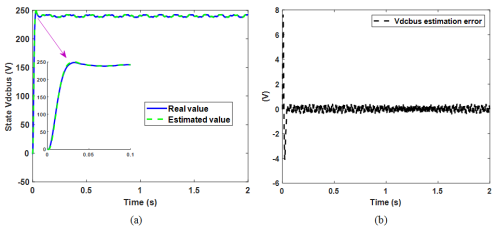
Figure 8. Response curves of the real and estimated DC bus voltage Vdc_bus (a) and the estimation error (b).
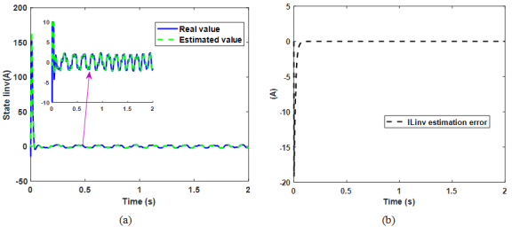
Figure 9. Response curves of the real and estimated inverter current Iinv (a) and estimation error (b).
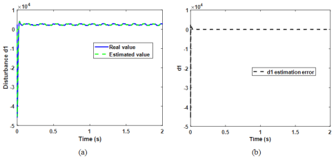
Figure 10. Real and estimated disturbance d1 curves (a) and estimation error (b).
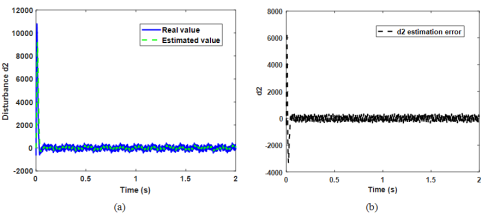
Figure 11. Real and estimated disturbance d2 curves (a) and estimation error (b).
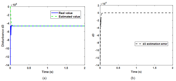
Figure 12. Real and estimated disturbance d3 curves (a) and estimation error (b).
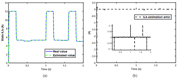
Figure 13. Response curves of the real and estimated boost converter inductance current ILb under Vpv variation (a) and estimation error (b).
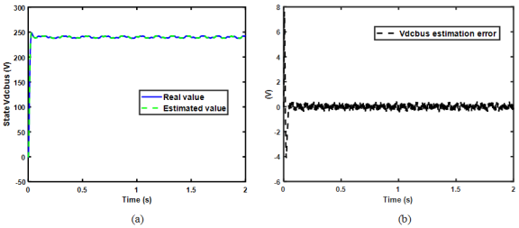
Figure 14. Response curves of the real and estimated DC bus voltage Vdc_bus under Vpv variation (a) and estimation error (b).
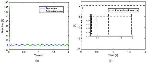
Figure 15. Response curves of the real and estimated inverter current Iinv under Vpv variation (a) and estimation error (b).
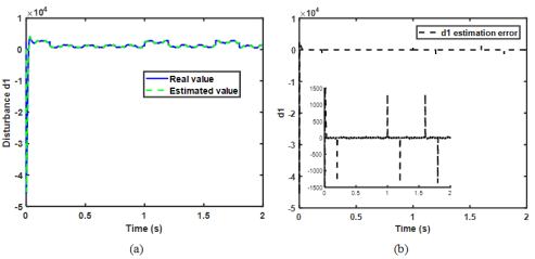
Figure 16. Real and estimated disturbance d1 curves under Vpv variation (a) and estimation error (b).
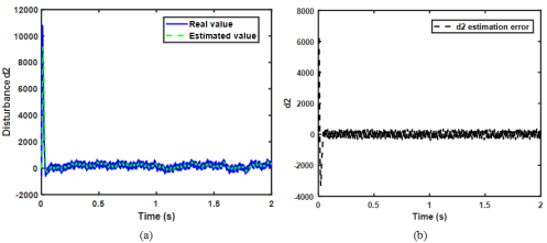
Figure 17. Real and estimated disturbance d2 curves under Vpv variation (a) and estimation error (b).
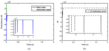
Figure 18. Real and estimated disturbance d3 curves under Vpv variation (a) and estimation error (b).
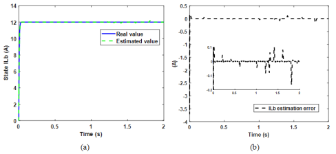
Figure 19. Response curves of the real and estimated boost converter inductance current ILb under Vg variation (a) and estimation error (b).
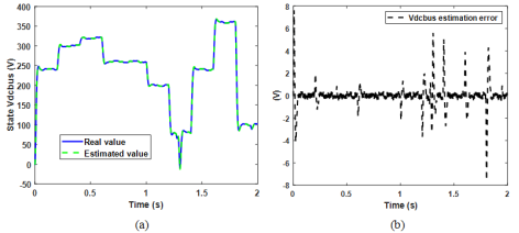
Figure 20. Response curves of the real and estimated DC voltage Vdc_bus under Vg variation (a) and estimation error (b).
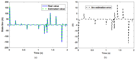
Figure 21. Response curves of the real and estimated inverter current Iinv under Vg variation (a) and estimation error (b).
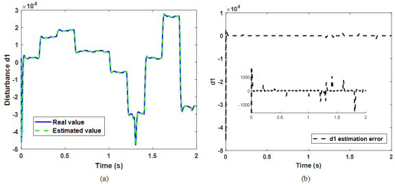
Figure 22. Real and estimated disturbance d1 curves under Vg variation (a) and estimation error (b).
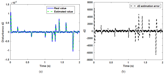
Figure 23. Real and estimated disturbance d2 curves under Vg variation (a) and estimation error (b).

Figure 24. Real and estimated disturbance d3 curves under Vg variation (a) and estimation error (b).
Information


 ;
;  and
and  , the equation (
 ;
;  and
and  ; equation (
 ;
;  and
and  into equation (